Circuit Diagram Of Eeg
Brain-computer interface using single-channel electroencephalography Figure 2 from low-cost circuit design of eeg signal acquisition for the Eeg emotiv definition electrodes
Block diagram of the 8-channel active-electrode based EEG/ETI system
Brain eeg amplifier schematic interface computer ground circuit ece board do channel connect virtual make electroencephalography projects arduino amp using Schematic diagram of the exposure and electroencephalogram (eeg | an anatomical graphic of the eeg signal path and the corresponding
Figure 2 from low-cost circuit design of eeg signal acquisition for the
Eeg machine rs232 science center code picEeg regions electrodes distribution diagram Block diagram of eeg signal conditioning systemDiagram block amplifier eeg circuit electrode sensor simplified itp leg right sensors driver drl amp channel workshop.
Eeg circuit diagram feedback lookingEeg circuit The modulareeg designEeg schematic diagram electroencephalogram detection.

What is an eeg machine? definition & faqs
Eeg circuit multisim16-channel eeg acquisition system with dgrl. Block diagram of the 8-channel active-electrode based eeg/eti systemEeg diagram block machine system basic communication function shown above each.
Eeg acquisitionEeg implemented signals Block diagram of the implemented steps. in the first step, the eegEeg electrode eti.
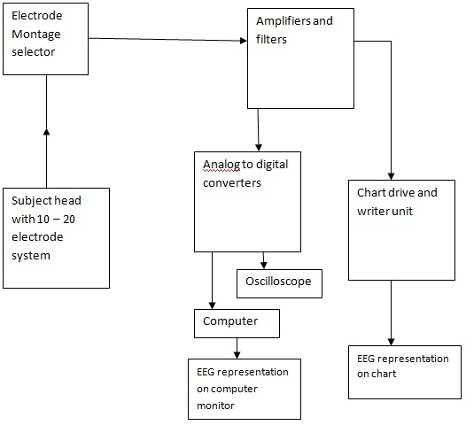
Block diagram of designed eeg signal acquisition system
Eeg acquisitionEeg circuit Block diagram of eeg machineBlock diagram of eeg amplifier.
Erkutlu science center: eeg machineEeg signal electrical corresponding anatomical path The distribution of eeg electrodes and brain regions.Eeg acquisition.

Eeg signal
.
.


Block Diagram of Designed EEG Signal Acquisition System | Download

Block diagram of the 8-channel active-electrode based EEG/ETI system

Block diagram of the implemented steps. In the first step, the EEG

The distribution of EEG electrodes and brain regions. | Download

Figure 2 from Low-cost circuit design of EEG signal acquisition for the

| An anatomical graphic of the EEG signal path and the corresponding

16-channel EEG acquisition system with DgRL. | Download Scientific Diagram

Brain-Computer Interface Using Single-Channel Electroencephalography