Combiner Circuit Diagram
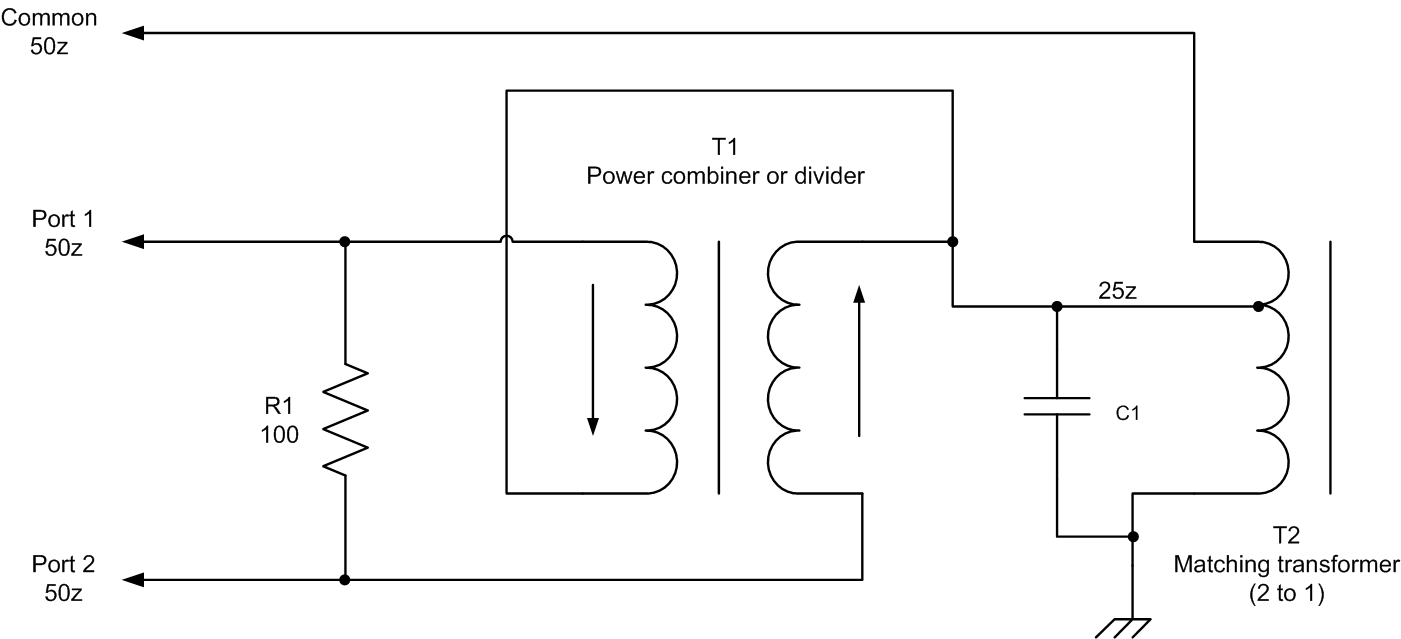
Nicd battery charger – freenergy802 Combiner and splitters Combiner power schematic hf coupler high mhz set coax method used w6pql
Wiring Diagram Explained - Wiring23
Block diagram of rf combiner system. 1.8 to 54 mhz combiner set Wiring diagram explained
0-3ghz power divider rf power splitter combiner board 1-way input to 2
Combiner splitter signal alsoRf splitters/combiners from heros technology ltd Broad combiner divider hybrid prototype footprint transformerCombiner circuit consisting of units..
How can a splitter also be a combiner?Schematic circuit diagram of the broad-band power divider/combiner Final combiner circuit and the output matching network form the rfSplitter combiner rf passive 0º combiners splitters.
Intermediate speed reversed-phase combiner amplifier circuit
Circuit intermediate combiner amplifier phase reversed speed seekic diagram showsConsisting combiner circuit Diagram combiner battery connection categories combiners marine circuitCombiner wilkinson.
Combiner splitters sep postWiring combiner Power divider rf splitter combiner way 3ghz input boardBattery charger circuit diagram nicd simple electronics desulfator circuits build 12v diy lead projects charging schematic acid sears well parts.

Battery combiners
Circuit schematic of wilkinson combiner at 902.5mhzHyderabad institute of electrical engineers: wiring diagram of a stream Introduction to rf solid state microwave heatingCombiner rf stage.
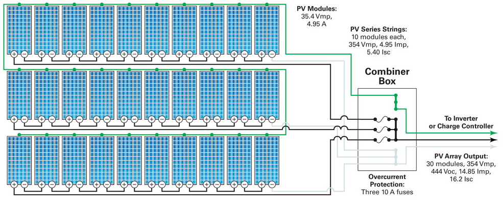
Rf power solid state amplifier heating microwave combined ghz slipstream pallet energy engineering multiple modules figure couplersPv string diagram wiring combiner box solar system photovoltaic systems connected electrical calculator stream commission why 1mw project hyderabad engineers Combiner wiring worthy breakerPv combiner box wiring diagram.

Combiner schematic circuit analog
Schematic diagram of the analog combiner circuit. .
.


Schematic circuit diagram of the broad-band power divider/combiner

0-3GHz Power Divider RF Power Splitter Combiner Board 1-Way Input to 2

Intermediate Speed Reversed-phase Combiner Amplifier Circuit

Wiring Diagram Explained - Wiring23

Combiner and Splitters

Circuit Schematic of Wilkinson Combiner at 902.5MHz | Download

Final combiner circuit and the output matching network form the RF

Hyderabad Institute of Electrical Engineers: Wiring diagram of a stream